
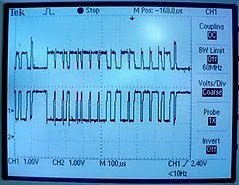
Using the dual trace feature on the oscilloscope capture the full pattern of the H-CAN & L-CAN. Identify which wire is the H-CAN and which is for the L-CAN.


Above: Graph shows Channel 1 (L-CAN) and Channel 2 (H-CAN)
Right: Yellow wire is L-CAN, and Blue wire is H-CAN
Looking at the dual trace oscilloscope readings, the patterns seem to be mirror images of each other. They share a common circuit and relationship.
The base voltage for channel 1 is 1v and increases to 1.6v when "talking" and when channel 2 is grounded.
The base voltage for channel 2 is also approximately 1v, and increases to about 2.6v when "talking" and when channel 1 is grounded.
When one channel "talks" the other/s listen, and only one channel can "talk" at a time. As the picture shows, when one channel is giving a signal, the other earths out, and vice versa.
Capturing patterns of different components.
 Right Indicator.
1. At this point where channel 1 is grounded for a longer period than previous is where channel 2 starts "talking" with very brief messages from channel 1.
2. At this point they stop talking and the original patterns return.
Most of the patterns on the different components are similar, and easily resemble this pattern.
Left Indicator

Reverse Light

Stop Light

Rear Wiper

Fuel Pump
Using the wiring diagram and CAN board, Identify the input/outout pins, wire colours. Relay or transistor for the right hand indicator and rear wiper.
Right hand Indicator:
Using the wiring diagram identify both voltage regulators that resemble the one that you built in TTEC4824.- Input pin number 7
- Output pin number 5
- Transistor U7
- Input pin number 9
- Output pin number number 7
- Transistor U14 & Relay RL4b
1. The voltage regulators that best resemble the one I built in TTEC4824 would be Voltage Regulators 7805.
- Input pins are numbers 1 & 2 (12v).
- Output pins number 14 on the integrated chip.
- Input pins are numbers 1 & 2.
- Output pin number 1 on the integrated chip.
The 12v input is coming into the voltage regulator, it charges the capacitor parallel to the IC. The IC regulates excess voltage and continues to resistor R29.
The current goes to the chip with LED which activates the transistor, in turn activating transistor U3 which activates the tail light.
No comments:
Post a Comment