Tuesday, November 30, 2010

CAN Multiplexing Worksheet

2003 Range Rover


Locate a twisted wire pair. Describe where they are located.
They can be located in the engine bay on the ABS Control Unit.

Record the waveform of one of the wires below. Make sure your time is small enough so you dont have "aliasing".

Wire Colour: Yellow/Brown
Time per Division: 20 micro-seconds
Volts per division: 1v per division


Wire colour: Yellow/black
Time per division: 20 micro-seconds
Volts per division: 2v


What is "aliasing"?
Aliasing is similar to distortion. When measuring something with a multimeter, like the twisted pair above, sometimes you do not get a clear reading because the readings were occurring too quickly for the multimeter to display on screen. So you would get a blurry visual. This is called aliasing because the multimeter literally displays an "alias" of what the actual reading should be.
Sometimes when the multimeter aliases a reading, it could appear as the average or RMS reading.

How do you know these waveforms are not "aliasing"?
Because they arent blurry or distorted. They are clear and easy to distinguish lines and the divisions.

Controlled Area Network Board


Using the dual trace feature on the oscilloscope capture the full pattern of the H-CAN & L-CAN. Identify which wire is the H-CAN and which is for the L-CAN.


Above: Graph shows Channel 1 (L-CAN) and Channel 2 (H-CAN)

Right: Yellow wire is L-CAN, and Blue wire is H-CAN


Looking at the dual trace oscilloscope readings, the patterns seem to be mirror images of each other. They share a common circuit and relationship.
The base voltage for channel 1 is 1v and increases to 1.6v when "talking" and when channel 2 is grounded.
The base voltage for channel 2 is also approximately 1v, and increases to about 2.6v when "talking" and when channel 1 is grounded.
When one channel "talks" the other/s listen, and only one channel can "talk" at a time. As the picture shows, when one channel is giving a signal, the other earths out, and vice versa.

Capturing patterns of different components.

Right Indicator.

1. At this point where channel 1 is grounded for a longer period than previous is where channel 2 starts "talking" with very brief messages from channel 1.

2. At this point they stop talking and the original patterns return.

Most of the patterns on the different components are similar, and easily resemble this pattern.

Left Indicator


Reverse Light


Stop Light


Rear Wiper


Fuel Pump


Using the wiring diagram and CAN board, Identify the input/outout pins, wire colours. Relay or transistor for the right hand indicator and rear wiper.

Right hand Indicator:
  • Input pin number 7
  • Output pin number 5
  • Transistor U7
Rear Wiper:
  • Input pin number 9
  • Output pin number number 7
  • Transistor U14 & Relay RL4b
Using the wiring diagram identify both voltage regulators that resemble the one that you built in TTEC4824.

1. The voltage regulators that best resemble the one I built in TTEC4824 would be Voltage Regulators 7805.
  • Input pins are numbers 1 & 2 (12v).
  • Output pins number 14 on the integrated chip.
2. Voltage Regulator U1
  • Input pins are numbers 1 & 2.
  • Output pin number 1 on the integrated chip.
Using the wiring diagram follow one circuit through from the input to the output. Note all the inputs/IC/relays/transistors and describe how the circuit operates.

The 12v input is coming into the voltage regulator, it charges the capacitor parallel to the IC. The IC regulates excess voltage and continues to resistor R29.
The current goes to the chip with LED which activates the transistor, in turn activating transistor U3 which activates the tail light.

On Car Exercises

Connect a scan tool to the vehicle you are testing and bring up the transmission information.

Scan tool: Multiscan +
Vehicle: 2000 BMW 318i

View the solenoids as the vehicle shifts up and down. Record which solenoids are on in which gears:


View the Torque Converter Clutch as you safely drive the vehicle. Record when it is on or off.
TCC On:
The torque converter clutch is on when accelerating.

TCC Off:
The torque converter clutch is off when the output shaft senses the output is slower than the input. So when you brake or use engine braking the TCC will turn off

What effects does the brake pedal have on the TCC operations?
The brake pedal will usually cause the TCC to disengage or turn off.

Electronic Transmission and Scan Tools

Abbreviations

PCM - Powertrain Control Module
TCC - Torque Converter Clutch
TPS - Throttle Position Sensor
ECT - Engine Coolant Temperature Sensor
VSS - Vehicle Speed Sensor
RSA - Transmission Range Fluid Pressure Switch Assembly
TTS - Transmission Temperature Sensor


Sketch a wiring diagram.


Which solenoids are "on when this vehicle is shifted into Drive and starts out in 1st gear?
1-2 and 2-3

Which solenoids are "on" when this vehicle automatically shifts into 2nd gear?
2-3

Which solenoids are "on" when this vehicle automatically shifts into 3rd gear?
None.

Which solenoids are "on" when this vehicle automaticallyshifts into 4th gear?
1-2


Shift solenoid malfunction: Describe what would happen if none of the solenoids came "on". Would the vehicle drive?
Yes it would be able to drive in fail safe mode; since 3rd gear doesnt need solenoid actuation to operate.

What gear would it be in?
It would be in 3rd gear.

How fast could the vehicle go?
It would start off very slow since it would be starting off straight in 3rd gear, and torque would be low; but would eventually reach speeds approximately 50km/h without riding it.

Could it have the power to climb a hill?
It might not, however if you get it going 50km/h constantly you probably could for a little while.

Codes: Pick 2 transmission codes out of repair information, and describe what the code means and what malfunction would cause the code.

1. Code 15
Engine coolant temprature sensor - Circuit voltage high when engine has been running more than 60 seconds and ECT has greater then 4.74 volts at less then 33 degrees.
Maybe a faulty temperature sensor, ECT has poor ground or connection, Coolant may need to be changed, radiator possibly broken, or maybe head gasket needs to be replaced.

2. Code 21
Throttle Position Sensor -Signal voltage stays 4.9v for about two seconds at engine idling.
Maybe a poor earth, faulty sensor, possibly the throttle/butterfly needs attention and cleaning.

Diagnosis.
For each code listed above, discuss what tests you could run to diagnose the problem

1. For the ECT sensor, Volt drop or resistance check it to see if its within proper manufacturer's specifications.

2. For the TPS, in code 21 it states that voltage stays at 4.9v for about 2 seconds at idle. This basically means that its at wide open throttle for 2 seconds while its idle.
You could connect an oscilloscope or multimeter to the TPS and volt drop or observe it. Or if its easily accessible, you could just pop the bonnet and monitor the throttle butterfly.

Using a Scan Tool

Using a scan tool go to the ABS live data screen and note all the sensors, data and what it is telling you.


Using the scan tool on the vehicle you have been assigned to. Go to the actuator test screen. Note below what component you have tested what happened when you tested that component and the test results.


FR LH Solenoid
1. It has a three stage solenoid
  • Up stage builds the pressure
  • Down stage releases the pressure
  • Hold stage holds the pressure
2. Motor actuates when it is actuated via the scan tool
3. When its on, the relay clicks
4. When its off, the relay clicks again

On Vehicle Testing


On the vehicle you were assigned does it use analogue or digital WSS?
The vehicle used an analogue WSS.

How did you conclude that the WSS was analogue?
Because it had only 2 wires. Digital WSS have 3 wires.

Measure the air gap for each WSS and state visual condition:
FL: 0.35mm - Appears to be ok. No damage.
FR: 0.35mm - Appears to be ok. No damage.
(Rear WSS were unaccessible because they were contained in the hubs).

Using an oscilloscope connect it to a WSS and record the pattern shown.
This is an analogue pattern.

Using the frequency scale on the multi-meter we got a reading of 265Hz.

In the above oscilloscope pattern:
Time = 10ms per division
Each signal cycle is approximately 4ms long.
1/F=T
F= 1/T
4ms=0.004s
F= 1/0.004= 250Hz - Slightly lower, but approximately the same reading we got off the multi-meter.

Monday, November 29, 2010

ABS Relays

The name of the relay or the switch that powers up the ABS ECU
K39

The name of the relay or switch that powers up the ABS pump
K100

The name of the relay or switch that sends power to the ABS HCU solenoids
K38

Relay wire identification:

The ECU pin number for the wire that brings in the power to the ABS ECU
1

The ECU pin number or other numbers for the wire that controls the relay for the ABS ECU
28

The pin number for the wire that brings in the power to the ABS pump
14

The pin number for the wire that controls the relay for the ABS pump
28

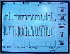
Capture a waveform that shows both the control circuit change when it turns on the relay, and the power swithcing on to power something in the ABS system.

Relay waveform:
Channel 1 is the switching circuit & Channel 2 is the control circuit.

1. The switching channel is at 12v.
2. The switching channel is grounded however the control circuit voltage doesnt increase. Possibly there was an interference in the switching signal which explains why voltage in the control circuit doesnt increase, but only slightly oscillates at the 0v mark.
3. Finally the relay works. The switching voltage is grounded, and voltage is flowing through to the control circuit as it shows in channel 2 the voltage is now at 12v.
4. The switch is off, and channel 1 is no longer grounded and returns to 12v. The control circuit is off and returns to 0v.


ABS Pump Relay Waveform:
Channel 1 is the switching circuit & Channel 2 is the control circuit.

1. Nothing is operating at this point. Voltages are 0v.
2. Switch is activated and the switching circuit reading goes up to 12v.
3. The relay begins to operate. The switching circuit voltage is grounded and the voltage on the control circuit increases to 12v.
4. The relay is shut off, and now the switching channel is no longer grounded.
5.The relay closes suddenly and induces these small oscillations of back EMF.
6. The switching circuit is off, and pulls to ground. This induces a voltage spike in the control circuit before it oscillates back to ground (unseen).

Discuss what is happening during the ABS self test.
When you first turn on the key, the ABS commences the self test to check
if all the ABS braking components are functioning and responding correctly.So once the key is turned, the ABS light comes on and current activates the ABS pump relay. The self check is in operation, and if anything has a fault, the ABS module wouldn't ground the fail-safe relay and warning light would stay on. Which would indicate to the driver there was something wrong.

Create a fault in the system by slowing down a WSS or safely shorting out an inductive WSS while you are applying the brakes (Don't short out a Hall Effect or Magneto-Resistive sensor). As you are applying the brakes, notice if the ABS pumps turns on, solenoids turn on, or if the hydraulic pressure changes in one of the brake circuits and shows up on the pressure gauge.

To manually slow down a single WSS, we used a plastic pipe
to press against the ring gear.
While pressing on the brake, we slowed down the WSS by pressing the plastic pipe against the WSS.
This makes the ABS control module think that this wheel is beginning to lock up. To prevent lockup the ABS system activates a solenoid that closes the inlet valve and open the outlet valve to stop excess brake pressure being applied to that wheel. By doing this, the wheel is not locked up and you maintain stability and steerability.


Catch an oscilloscope pattern when an ABS solenoid has actuated. What is the pin name of the solenoid? and how did you do it?

This graph on the right identifies the pins:
LF = 1B
RF = 1C
RL = 1D
RR = 1A


On the left is the oscilloscope pattern captured from 1A (RR).
We connected the oscilloscope to the solenoid wire in the control module guided by the circuit diagram and grounded it. We operated the ABS modulator and pressed the brakes. We used the plastic pipe to manually slow down the WSS connected to this solenoid. This pattern was the reading.